Detailed Explanation of BYD’s Heat Pump Air Conditioning Technology for Pure Electric Vehicles
01
Cooling and Heating of Heat Pump Air Conditioning
A heat pump air conditioning system is a highly energy-efficient device capable of both cooling and heating. During heating, it operates in reverse cycle mode, forcing heat to transfer from a lower-temperature object to a higher-temperature one. It consumes only a small amount of reverse cycle work while delivering a significant amount of heat, thereby achieving energy savings.
As shown in Figure 1, the heat pump air conditioning system mainly consists of an electric compressor, three heat exchangers (outdoor condenser, indoor condenser, and indoor evaporator), two solenoid valves (cooling solenoid valve and heating solenoid valve), two electronic expansion valves (cooling electronic expansion valve and heating electronic expansion valve), as well as refrigerant pressure and temperature sensors.
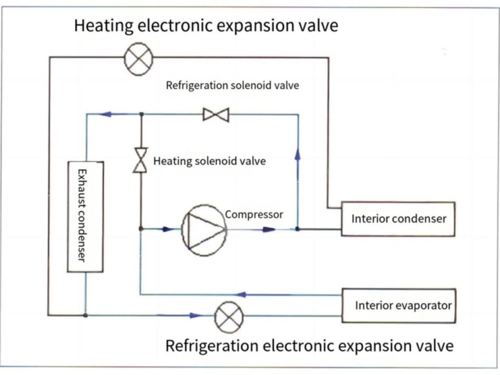
Figure 1 Schematic Diagram of the Heat Pump Air Conditioning Cooling Principle
The air conditioning compressor is driven by high-voltage AC power, typically of the fixed-displacement, scroll type. It supplies the required refrigerant flow to the air conditioning system by varying the motor speed. The solenoid valves are on/off types, activating and opening the flow path when energized. The electronic expansion valve operates by following control signals to rotate the stepper motor, which drives the needle valve’s axial movement. By adjusting the valve opening area, it regulates the refrigerant flow to match the thermal load.
1.Cooling Principle
When the heat pump air conditioning system operates in cooling mode, the cooling solenoid valve and cooling electronic expansion valve (shown in Figure 1) are activated. High-temperature, high-pressure refrigerant discharged from the compressor passes through the cooling solenoid valve and enters the outdoor condenser, where it exchanges heat with the outside air and condenses into a high-pressure, medium-temperature liquid. After being throttled by the cooling electronic expansion valve, the refrigerant enters the indoor evaporator, absorbs heat from the cabin, and evaporates into a low-pressure, low-temperature gas before returning to the compressor, completing the cooling cycle.
2.Heating Principle
In heating mode, the heating electronic expansion valve and heating solenoid valve (shown in Figure 2) are engaged. High-temperature, high-pressure refrigerant from the compressor flows into the indoor condenser, releasing heat to warm the cabin and condensing into a high-pressure, medium-temperature liquid. The refrigerant then passes through the heating electronic expansion valve, where it is throttled before entering the outdoor evaporator. Here, it absorbs heat from the external environment, evaporating into a low-pressure, low-temperature gas. Finally, the refrigerant returns to the compressor via the heating solenoid valve, completing the heating cycle.
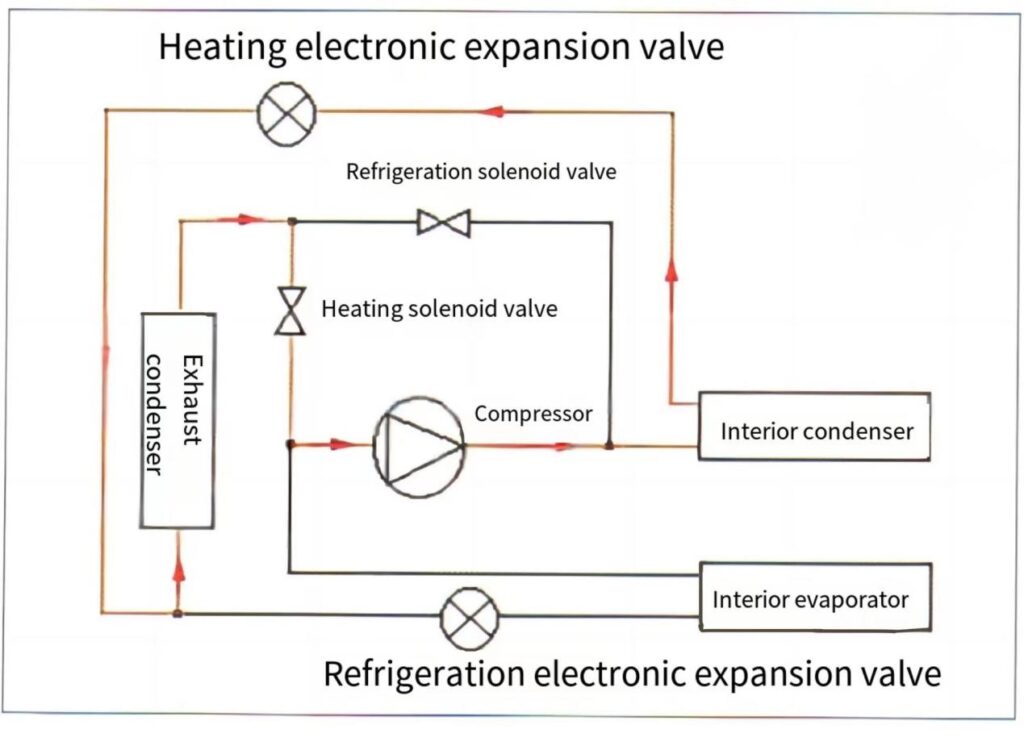
Figure 2 Schematic Diagram of the Heat Pump Air Conditioning Heating Principle
02
BYD Dolphin’s Heat Pump Air Conditioning System
In September 2021, BYD launched the Dolphin—the first model of its all-electric 3.0 platform Ocean Series. This vehicle was the first to be equipped with a heat pump air conditioning system, significantly improving the overall efficiency of the thermal management system.
1.Composition of the Dolphin’s Heat Pump Air Conditioning System
As shown in Figure 3, the heat pump air conditioning system of the Dolphin car mainly consists of an electric air conditioning compressor (with a maximum power of 6kW), an electronic fan, a motor radiator, an external condenser, an internal condenser and internal evaporator, a direct cooling and heating plate for the power battery, a gas-liquid separator, a thermal management integrated module, and a plate heat exchanger (located below the thermal management integrated module), etc. The refrigerant is R1 34a (R410a is used in some pure electric models of BYD).
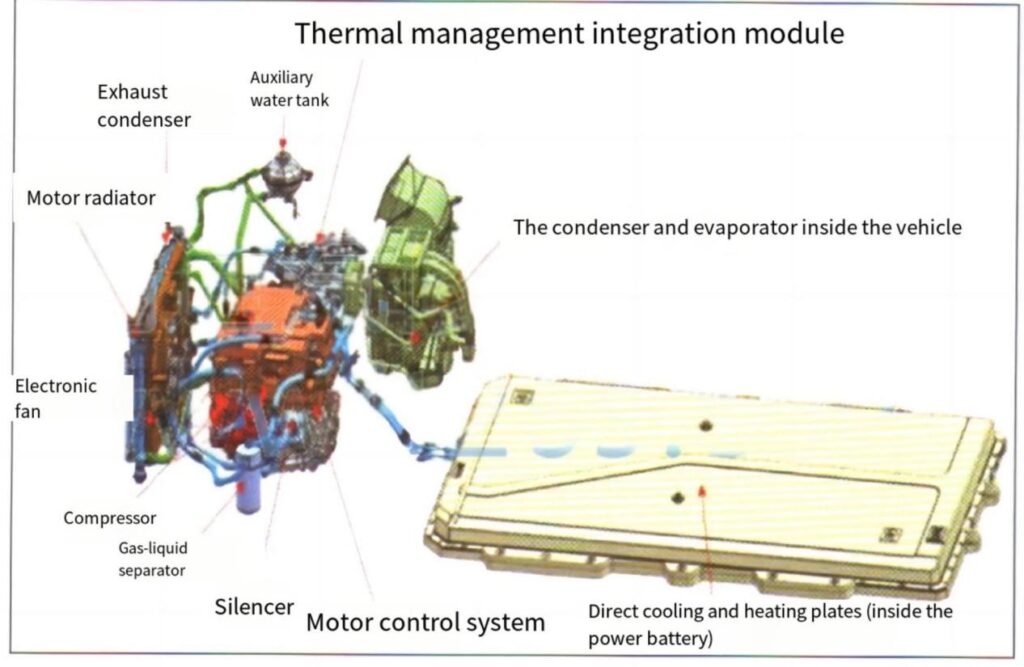
Figure 3 Composition of the Dolphin’s Heat Pump Air Conditioning System
The thermal management integration module incorporates 6 solenoid valves, 3 electronic expansion valves (Figure 4), and 9 refrigerant pipe connections (Figure 5).

Figure 4 Thermal Management Integration Module

Figure 5 Pipeline Connections of the Thermal Management Integration Module
2.Working Principle of the Dolphin’s Heat Pump Air Conditioning System
The schematic diagram of the Dolphin’s heat pump air conditioning system is shown in Figure 6. In the diagram:
PT-1 and PT-2 represent two refrigerant pressure and temperature sensors
P-1 indicates a refrigerant pressure sensor
T-1 and T-2 denote two refrigerant temperature sensors

Figure 6 Schematic Diagram of the Dolphin’s Heat Pump Air Conditioning System Principle
The Dolphin car heat pump air conditioning system has eliminated the high-pressure PTC heater of traditional electric vehicles and replaced it with a low-pressure air-heated PTC heater (1kw), which is used for auxiliary heating in extremely low-temperature environments.
In addition to the functions of cooling and heating inside the vehicle, the Dolphin car heat pump air conditioner has also achieved the world’s first direct cooling and heating of the power battery through the refrigerant, as well as the utilization of heat from the drive motor, motor controller and other electric drive units. It has also realized the intelligent comprehensive thermal management of the entire vehicle. The Dolphin car equipped with heat pump air conditioning technology has a winter range increase of more than 10%. The vehicle covers a wide temperature range of -30 to 40℃, and the energy consumption per 100 dry meters has been reduced to 10.3kWh at the lowest.
(1) Heating Mode Operation
When the vehicle is driven (or stopped) at low temperatures, turn on the air conditioning system for heating. The heat pump air conditioning system activates the electric compressor. The heating electronic expansion valve works, and both the water source heat exchange solenoid valve and the air conditioning heating solenoid valve are open. The refrigerant releases heat through the condenser inside the vehicle and absorbs the heat from the drive motor, motor controller and other electric drive units through the plate heat exchanger. In extremely low-temperature conditions, the PTC heater can be turned on for auxiliary heating to increase the applicable temperature range of the heat pump air conditioner.
When the air conditioner is used for heating, the flow path of the refrigerant is as follows: compressor → condenser inside the vehicle → heating electronic expansion valve → water source heat exchange solenoid valve → plate heat exchanger → air conditioner heating solenoid valve → gas-liquid separator → compressor (Figure 7).
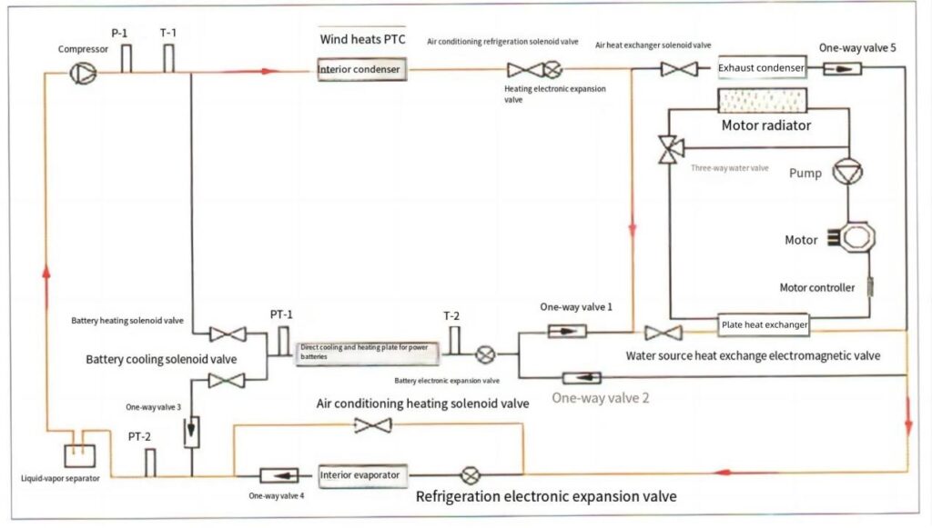
Figure 7 Heating Mode
(2)Battery heating:
When charging in a low-temperature environment, to shorten the charging time, or when the vehicle is driving in low temperatures, to improve the overall power performance of the vehicle in low temperatures, the heat pump air conditioner works to directly heat the battery. At this point, the battery electronic expansion valve opens to work, and the battery heating solenoid valve, water source heat exchange solenoid valve and air conditioning heating solenoid valve are all open. The refrigerant absorbs the residual heat of the electric drive unit through the plate heat exchanger and heats the direct cooling and direct heating plate of the power battery.
When the battery is heated, the flow path of the refrigerant is as follows: compressor → battery heating solenoid valve → power battery direct cooling and heating plate → battery electronic expansion valve → Check valve 1→ water source heat exchange solenoid valve → plate heat exchanger → air conditioning and heating solenoid valve → gas-liquid separator → compressor (Figure 8).

Figure 8 Power Battery Heating Mode
(3)Air conditioning heating and power battery heating are carried out simultaneously
When the vehicle is traveling at low temperatures or charging at low temperatures, if it is necessary to heat both the passenger compartment and the power battery simultaneously, the heat pump air conditioning system will activate the electric compressor, and the heating electronic expansion valve and the battery electronic expansion valve will open to work at the same time. The water source heat exchange solenoid valve, the battery heating solenoid valve, and the air conditioning heating solenoid valve will all open to absorb the residual heat of the electric drive unit. The condenser inside the vehicle and the direct cooling and heating plate of the power battery release heat. If necessary, the PTC heater can be turned on for auxiliary heating (refer to Figures 7 and 8 for the flow direction of the refrigerant).
(4)Air conditioning cooling
When the vehicle is driving (or stationary) at high temperatures, the air conditioning system is turned on for cooling. The heat pump air conditioning system activates the electric compressor, and the refrigeration electronic valve and expansion valve work. Both the air conditioning refrigeration solenoid valve and the air heat exchange solenoid valve are open. The refrigerant releases heat through the external condenser of the vehicle, and the internal evaporator absorbs the heat inside the vehicle.
When an air conditioner is cooling, the flow path of the refrigerant is: the compressor. In-vehicle condenser → Air conditioning refrigeration solenoid valve → air heat exchange solenoid valve → Check valve 5→ refrigeration electronic expansion valve → in-vehicle evaporator → Check valve 4→ gas-liquid separator → compressor (Figure 9).
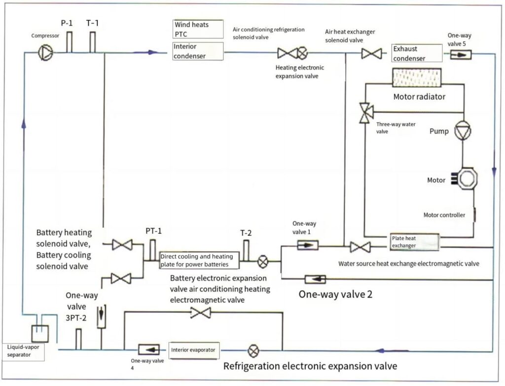
Figure 9 Air conditioning cooling
(5) Cooling of power batteries
When charging, especially at high power, to prevent the temperature of the power battery from getting too high, the heat pump air conditioner works to directly cool the power battery. When the vehicle is in motion, if the temperature of the power battery exceeds the set value, the heat pump air conditioner also starts to work. At this point, the battery electronic expansion valve opens to work, and the air conditioning refrigeration solenoid valve, air heat exchange solenoid valve and battery cooling solenoid valve are all open. The refrigerant releases heat through the heat exchanger outside the vehicle and absorbs heat through the direct cooling and heating plate of the power battery.
When the power battery is cooling, the flow path of the refrigerant is as follows: compressor → in-vehicle condenser → air conditioning refrigeration solenoid valve → air heat exchange solenoid valve → Check valve 5→ Check valve 2→ battery electronic expansion valve, power battery direct cooling and heating plate → battery cooling solenoid valve, check valve 3→ gas-liquid separator compressor (Figure 10).
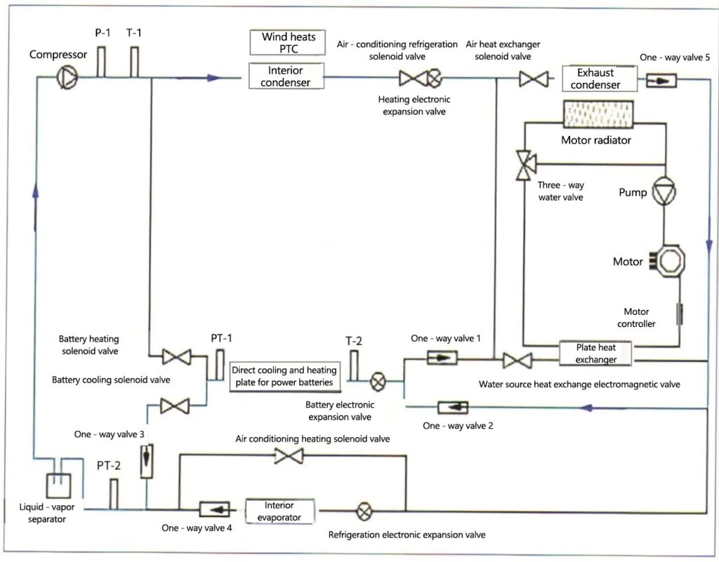
Figure 10 Cooling of power batteries
(6) Air conditioning and power battery cooling are carried out simultaneously
When a vehicle is charging or in motion, if both interior cooling and battery cooling are required simultaneously, the heat pump air conditioning system will operate. At this time, both the battery electronic expansion valve and the cooling electronic expansion valve will open simultaneously, and the air conditioning cooling solenoid valve, air heat exchange solenoid valve, and battery cooling solenoid valve will all be open (refer to Figures 9 and 10 for the flow direction of the refrigerant).